The aim of the study was to build a low voltage high current electronic converter for 3 phase machines, dedicated for a particular light electric vehicle application with synchronous reluctance machine. The converter was designed in Altium Designer software. It is based on using IRF6448PBF MOS transistors, rated at 150V and 200A. Actually, the machine that needs to be supplied is rated at 48V and about 45A peak current. the converter's gate drivers are IR2111 with 620ns deadtime and also, fast optocouplers ensure the separation between the control board and the electronic converter. The control board is supplied from National Instruments, and it is a General Purpose Inverter Controller (GPIC). The control program is setup in LabVIEW FPGA, and it is uploaded on the SPARTAN 6 type FPGA of GPIC.
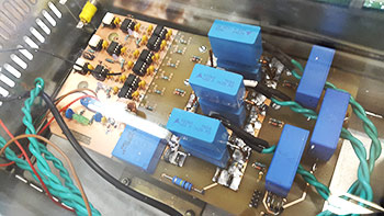
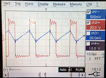
As it can be seen in the picture, strong capacitive snubber level is ensured to limit the switching spikes that appear at high currents.
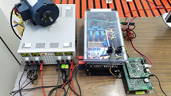
Also, the converter was designed to have current sensing on board, and also a voltage transducer is installed to monitor the DC link voltage. The supply of the low voltage stage (drivers and measurement) is fed by a low power precise power supply, and the DC link is fed from a 5kW programmable power supply.
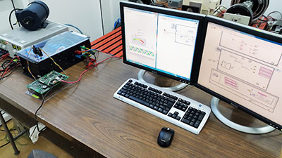
The testbech can be seen in the figure, with the power converter, the GPIC , the monitoring computer and the load of the converter.
For more details regarding this study, feel free to contact me or to check my journal and conference publications.